This photo shows the EB104 circuit board mounted on the heatsink subassembly. A bimetallic thermal sensor (with yellow leads) is bolted to the heatsink. It's visible just below a VSWR sensor fitted within the small aluminum box at the edge of the heat sink (top of photo).
Since this photo was taken, the 10-ohm feedback resistors have been upgraded, using paralleled 43-ohm 2W film resistors. This ensures a cool running resistor pack, even at full power, which is especially important for high duty-cycle CW.
Click on this image for a magnified view.
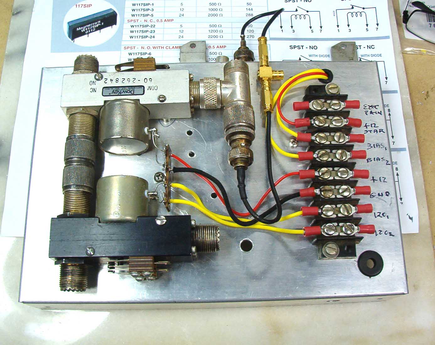
The amplifier uses a number of relays to route RF, disconnect drive in the event of a fault, and to enable fast break-in QSK keying. The top side of the relay module is shown here.

VSWR protection for the MOSFETs is provided by the SWR detector. It triggers an SCR in the event of high SWR.
An LED bargraph meter, based on an LM3914 chip, along with a pair of single LEDs, indicates VSWR (up to 3:1), as well as (a) an SCR "fired" indication (a fault), and (b) whether the main keying relay is enabled.
Click on the image of the panel indicator to view a detailed schematic of the LM3914 detector that feeds the SCR-relay circuit.
When the SCR triggers, a relay opens and removes (a) RF drive from the exciter, and (b) bias from the four MRF150 MOSFETs. Here's what the SCR module looks like.
Click on this image to view a detailed schematic of the SCR-relay circuit.
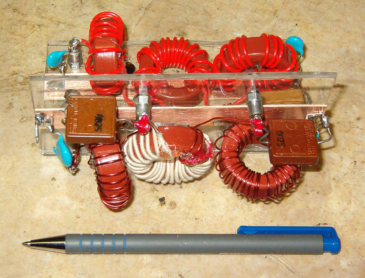
The next pair of photos show the amplifier's outboard lowpass filter assembly, which is required to suppress odd-order harmonics, thereby meeting FCC regulations (Part 97, Paragraph 307). This manually switched box ultimately will be upgraded to a logic-relay board driven by the STAR transceiver. Two LPF assemblies are shown, assembled on Plexiglas.
Click here for a computer-assisted LPF design tool.


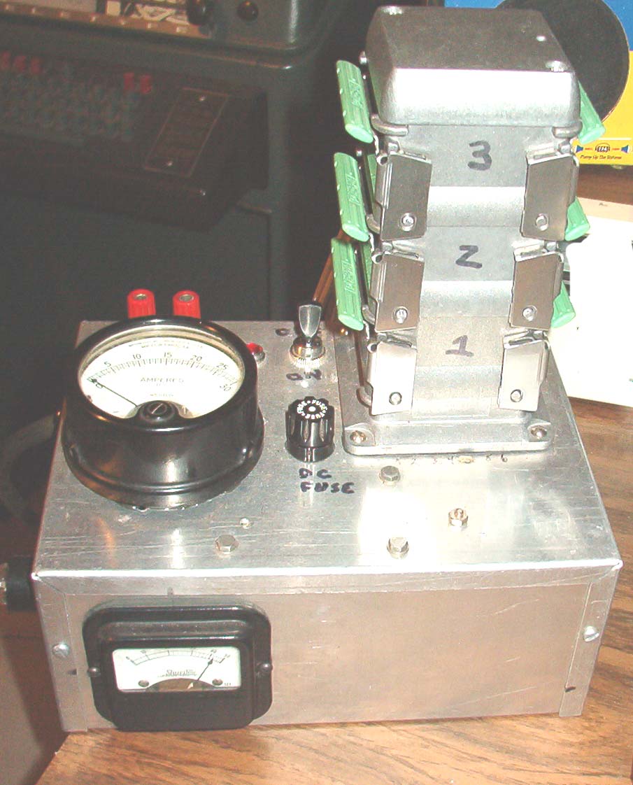
The following photo shows the desktop control box for the amplifier's MIL-surplus 50V at 34A switching power supply.
The controller box includes a 0-30A DC ammeter, a 0-50V DC voltmeter, and a time-delay relay for "soft start" power-up protection. The stacked connectors are Phoenix Contact Duplicon industrial types.

Click here for the schematic diagram of the control box wiring.
Click here for the overall relay and control circuit wiring diagram.
Click here to view the system's reed relay circuit diagram, driven by the STAR transceiver's timing controller.
Click here to return to this Web site's home page.