A Softrock circuit board---sourced by Five-Dash, KB9YIG, Tony Parks, as an $89 kit (up from $74)--- makes for a simple, but quite high-performance, software defined radio (SDR) at AI2Q.

The place for learning more about Softrock theory and construction is WB5RVZ's Web site. (There are more useful links at the end of this presentation).

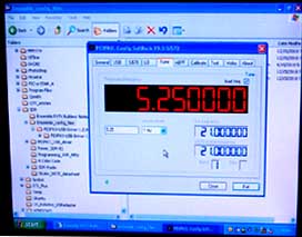
For its part, my configuration runs free SDR software. There are quite a few compilations to choose from and experiment with (more on this later).

The Hardware

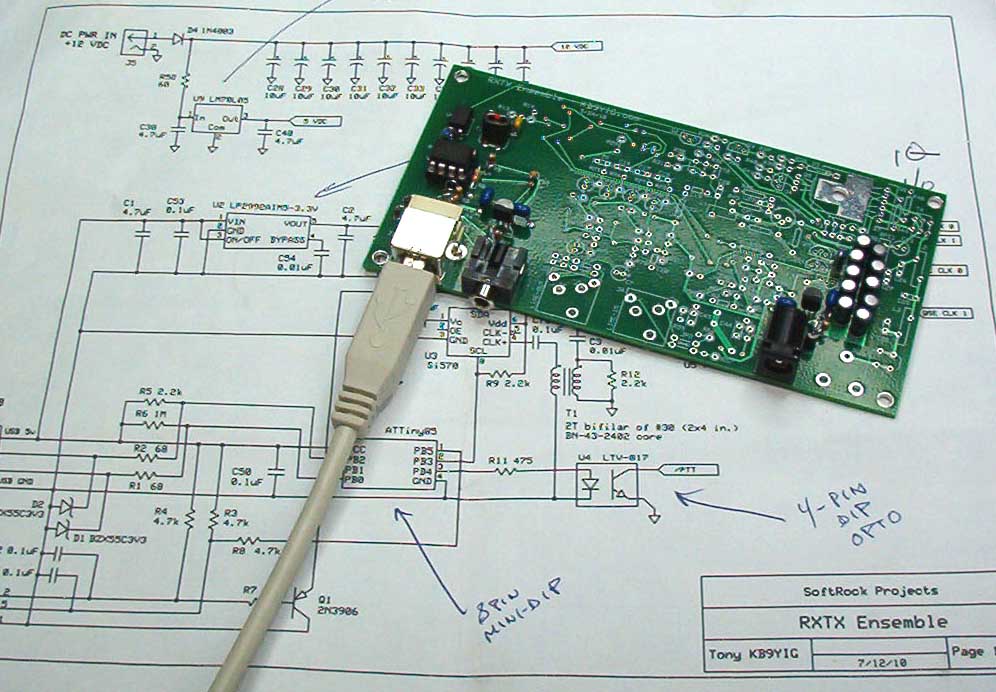
The Softrock Ensemble RXTX hardware implements a quadrature sampling encoder (QSE) and a quadrature sampling detector (QSD) that works in conjunction with an outboard USB-compatible soundcard digitizer. My Creative Labs USB soundcard plug-in communicates with a Windows XP platform running an AMD Athlon processor clocking at 2.8-GHz, with 1024 Mbytes (1 Gbyte) of DRAM.

The QSE and QSD circuits support Transmit and Receive functions, respectively.

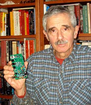
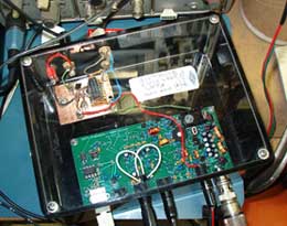
The photo to the right shows the Ensemble RXTX mounted in a small enclosure, along with a control relay board. The relay mutes some pesky sidetone generated by the software.

The enclosure houses power, USB, and I/O connectors, as well as a BNC connector for the antenna port.

My Ensemble RXTX is wired for Receive and Transmit coverage of the 30, 20, and 17 meter bands, but it works well transmitting on 40 meters, too. The receiver's lowpass filter permits receive-only operation down through 160 meters with very good performance.

Arithmetic processing

The Ensemble hardware is partially controlled by an 8-pin miniDIP-packaged Atmel ATtiny85 AVR microcontroller. The AVR comes from KB9YIG pre-programmed as a USB device that gives the SDR push-to-talk, keying, and VFO control from the host PC. Power for the ATtiny85 is also derived from the PC's USB bus.

The VFO, based on a Silicon Labs Si570 chip, generates a signal that's 4x the frequency of the desired center frequency of the SDR. The output of the oscillator is fed to a divider, where the signal is divided by four, yielding two signals that are identical except that they are 90 deg. out of phase (thus the term quadrature). These signals clock the system's Receive and Transmit switching mixers.

Here's the Ensemble RXTX partially assembled, with the USB VFO under initial test.

This screen shot shows the Piezo crystal-based Si570 under test using a configuration utility running under Windows. Note that the VFO is oscillating at 5.25 MHz and generating a 4x signal at 21 MHz.

The next image shows the quadrature mixer probed for initial test.

Here's the 90-deg. phase shift displayed on my dual-trace oscilloscope.

In Receive operation, the mixer chip outputs the product and difference signals of the incoming received RF against the QSD clock. The effect is to down-convert the incoming RF into quadrature frequencies ranging from 0 to about 100 kHz.

The quadrature pairs from the mixer, identical in all respects except phase, are amplified and filtered into audio and infra-audio and then delivered to the Ensemble's stereo audio jack. The PC's sound card then performs its SDR magic from these analog in-phase and quadrature (I and Q) signals.

The PC's sound card digitizes the analog I/Q signals for subsequent arithmetic processing by the SDR software running on the PC. The PC then handles modulation and demodulation, filtering, AGC, and the human interface, to name just a few functions and processes.

Transmit functions are essentially the reverse of the Receive functions. For RF output when transmitting, a 1-watt on-board FET driver amplifies the modulated RF output from the Transmit mixer. In my shack, this low-level RF is fed to an outboard bipolar transistor push-pull amplifier and lowpass filter assembly that boosts output power to about 35 watts.

Click here to go to Page 2.

Click here to return to home page.