The Heart of The Transceiver
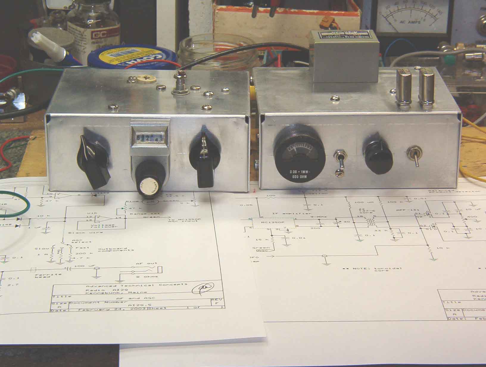
The heart of the AI2Q 75-meter KISS transceiver (the dual-module receiver section shown above) is its VFO.
Unlike previous homebrew rigs, where construction began at the receiver's audio output and proceeded "backwards" towards the front-end, it was deemed appropriate to build and test a VFO with demonstrable stability---and do it before construction of the rig's other modules began.
The VFO Circuit
A number of textbook circuits were considered for the rig's VFO, and the junkbox was then scrutinized carefully for optimum components, especially those that would be temperature-stable. Polystyrene dielectric and glass dielectric fixed capacitors (military types) were chosen, along with a ceramic slug-tuned coil form.
A Colpitts oscillator forms the basis of the VFO. The main tuning capacitor is an old-fashioned heavy Hammarlund 50-pF variable. It's augmented by a "bandspread" circuit consisting of a 10-turn pot back-biasing a pair of ordinary 1N4002 power diodes.
Varying the bias voltage on the diodes alters their depletion region, and thus their capacitance. Surprisingly, the diodes work well as varicaps. Overall, the VFO only drifts about 40-Hz/hr after a short initial warmup.
The mechanical variable capacitor, and the VFO's inductor, are mounted directly on a subchassis, to ensure mechanical stability. Click here for a photo showing these components under test.
In contrast, the VFO buffer circuitry is mounted on a circuit board. Click to continue.