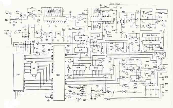
In years past the UTU was extensively used on AMTOR, and the performance of its 170-Hz-shift AFSK front-end filtering was deemed quite good---even under adverse conditions.
In this TU (terminal unit) application the detected data is picked off at the UTU's test point H (diagram below), and then routed to the logic board at terminal J on its input header (upper right of the diagram shown here).
The UTU's EXT SPKR (external speaker) jack is used to conveniently route the data out of the UTU. This involved cutting a single trace that originally tied the AUDIO IN jack to the speaker jack. The speaker jack is then freed up to act as a DATA OUT jack. This "mod" is easily reversible.
Click on the schematic (right) to see the logic board.

The UTU uses a pair of National Semiconductor MF-10 switched-capacitor filter chips, clocked by the UTU's microcontroller. The UTU also makes use of op-amp limiters and an op-amp detector. Once the incoming AFSK signal is converted to data levels, the resulting serial bitstream is buffered by a CMOS 4069 chip, and then routed directly into the UTU's micro for firmware processing.
As noted above, the raw detected data is picked off at the UTU's test point H, and then routed to the logic board at terminal J on its input header (diagram above). The 4011 NAND gate U6 is powered from the logic board's 5-V rail, thereby limiting its output to a 5-V TTL level to drive U3C.
This scheme permits the Model 28 to operate simultaneously with the UTU. The UTU feeds ASCII to a computer (terminal) as the Model 28 prints received Baudot.
Click on the schematic (right) to see the logic board connection.
Click here to return to the AI2Q home page.
