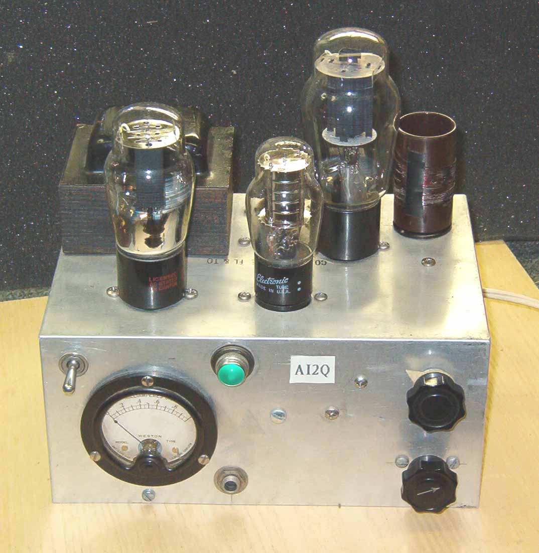
| Back to the future! Folks have asked me about my 6L6 Colpitts-oscillator transmitter that I use on 80 and 40 meter CW during the Antique Wireless Association on-the-air tests. It's a replica of a 1938 transmitter. Here's a photo of the little rig. It was built on my kitchen table during a time when I was a cliff dweller in the mid-1980s. The transmitter uses a glass 6L6 (so you can enjoy the glow of the filament), and a VR-150 voltage regulator tube (its gas glows with a nice purple hue). The DC power is derived from a Type 80 full-wave rectifier tube. The rig is crystal-controlled, with band changes made through the use of plug-in coils. It develops about eight watts of RF. This rig, and its companion receiver, along with a vintage schematic and Mac key, were featured in QST Magazine, December 1997, pg. 20. |
 |
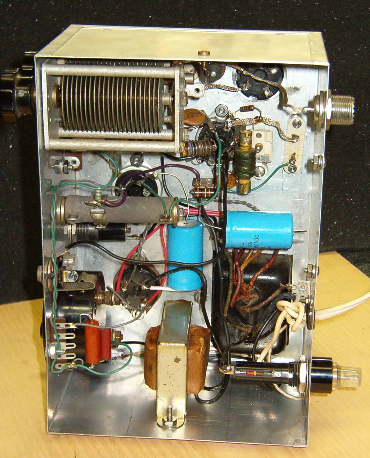
| Here's a view of the innards of
the 6L6 rig. Some concessions to modernity were made in its design. For example, although it uses plug-in coils, the tank circuit is part of a pi-network. That permits easy matching to 50-ohm unbalanced transmission lines. For the same reason, a standard SO-239 coaxial output connector is used, as well as an old TV-style power transformer. Likewise, the rig includes an indicating fuse holder, and modern tubular high-voltage electrolytic filter capacitors. When signing off, I usually wave my hand over the 6L6, "wobbulating" the rig's frequency for a unique final note! |
 |
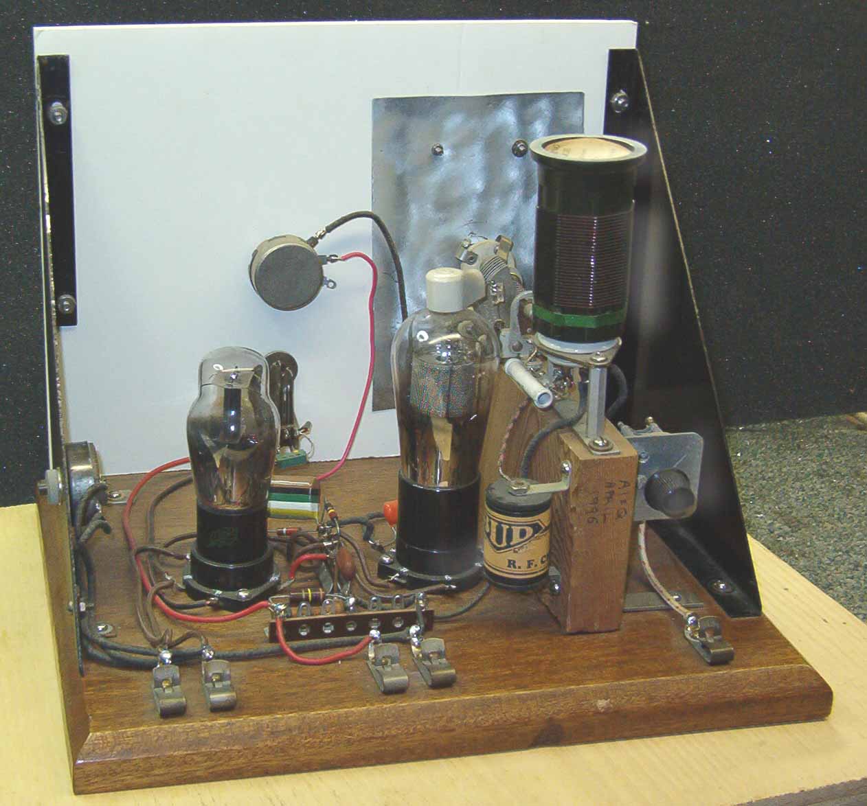
| This is a view of the guts of a
companion receiver to the 6L6 transmitter. It is a
replica of a "schoolboy's" regenerative set
that was popular in the late 1920s through the 1940s. Like the transmitter, band changes are effected by installing the appropriate plug-in coils. The regenerative tuner uses a Type 24 pentode tube. It's followed by a Type 27 triode audio amplifier. |
 |
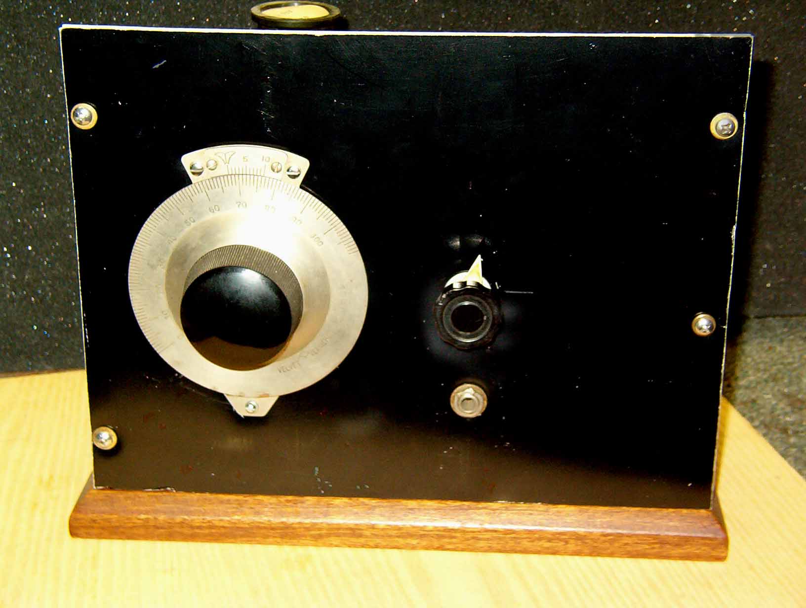
| Here's a view of the receiver's
front panel. Simple enough, eh? There's just a tuning
knob and regneration control. Nonetheless, there is a bit of a technique that you need to learn to set the regeneration at the right point and get the receiver to play. |
 |
 Click here to return to AI2Q home page. |
Click here to review the 6L6 transmitter's
schematic. Click here to see the regenerative receiver's schematic diagram. |