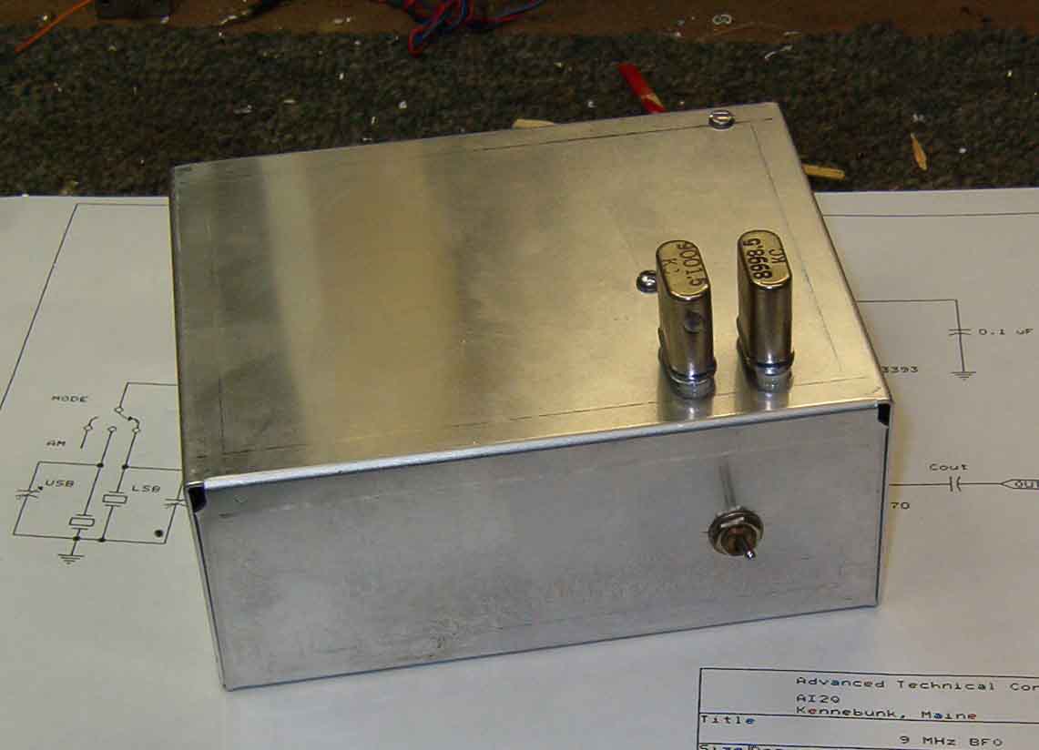
| The 9-MHz BFO uses a pair of
crystals in order to place the "phantom
carrier" outside the rig's 9-MHz IF filter bandpass,
while putting the selected sideband within the filter. The two crystals provide product detector injection for either upper sideband detection, or lower sideband detection. The BFO output is also picked off and routed to an external panel connector for application to the transceiver's balanced modulator. The crystals are mounted in sockets, and are manually switched using a panel-mounted toggle switch. Although diode switching was considered in order to permit remote placement of the BFO circuit board, the small aluminum enclosures ensured that all leads between the board and the toggle switch would be sufficiently short. |
 |
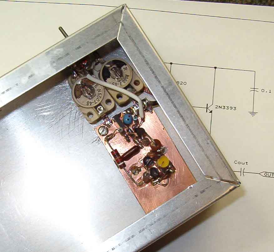
| Electro-mechanical switching of the crystals proved satisfactory. The photo shows some of the lead dress with the board initially mounted under the chassis. The two variable capacitors permit precise trimming of the BFO frequency. |  |