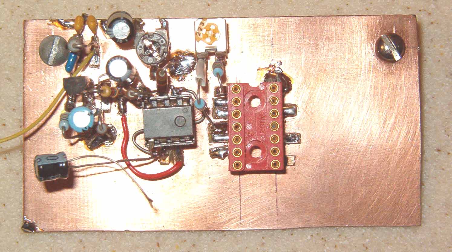
| Here you can see additional
components installed on the mic.-amp/balanced modulator
board. The red screw-machined 14-pin DIP socket accommodates the LM1496 Gilbert-cell mixer chip that serves as the rig's doubly-balanced modulator. The LM1496 chip accepts audio from the LF356 op-amp and mixes it with 9-MHz energy from the BFO to produce a double-sideband signal at the 9-MHz IF. The small yellow pot at the top edge of the board is the Balance pot. Notice that not all of the IC's pins are utilized. That simplifies placement of the closely-spaced "Manhattan" pads. Makes it easy for beginners before tackling surface-mount technology parts. Click here to see the updated (Jan. 2004) schematic diagram for the balanced modulator. |
 |
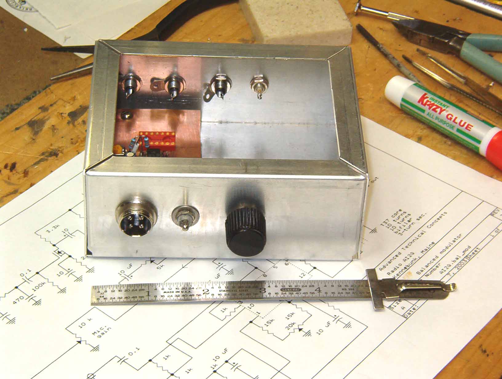
| The partially completed modulator board is temporarily installed in the transmitter section's module in order to check for proper fit. |  |
| At this stage of construction,
the transmitter module's front panel includes a
microphone connector (with provision for push-to-talk), a
DPDT toggle switch for SSB/CW(tune) selection, and a Mic/CW
Level potentiometer. The rear panel includes RCA phono plugs for BFO input, and IF in/out signal routing. Also installed is a 0.001-uFd power feedthrough for routing +Vcc into the module. |
 |
| Click here to return to previous page. | Click here to see completed SSB generator. Click here to return to home page. |