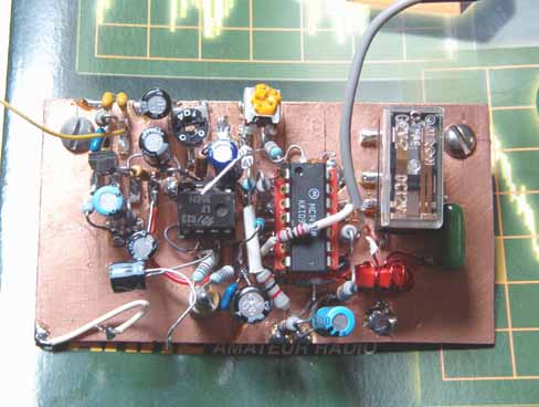
| Here's the nearly completed
SSB generator board, with mic. amplifier, LM1496-based
balanced modulator, and DIP-style TX/RX changeover relay
in place. Not shown (added later) is a 1N4001 counter-EMF diode across the relay coils, and additional signal and DC routing. |
 |
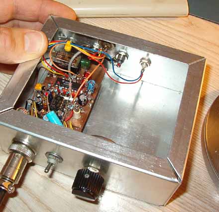
| This photo shows the SSB
generator board in place in the aluminum TX chassis, with
signal and DC wiring to rear-panel I/O connectors in
place. The toggle switch selects CW (carrier) or SSB operation, with the knob adjusting a pot to set the level of the DC offset for the carrier level, or microphone amplifier audio. Either can feed the balanced modulator. |
 |
| Connecting a microphone and listening to the signal on the shop receiver (an R-392 tuned to 9-MHz) is a satisfying experience. The DSB audio sounds crisp and clean, with good carrier suppression (some BFO radiation and suppressed carrier can be heard on the test receiver). | 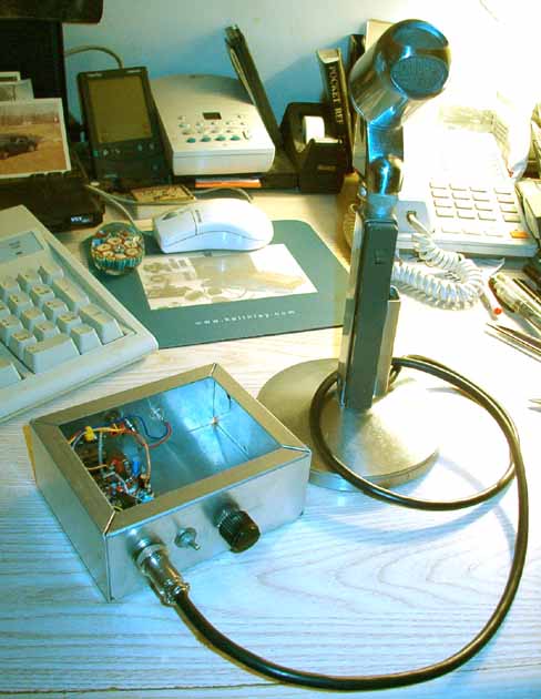 |
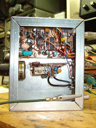
| Here's a photo of
the TX-mixer module with the transmitter-mixer board
installed. Click here to see an image of the TX-mixer board. Click here for the schematic of TX-mixer and RF pre-driver stages. Click here to see the improved un-tuned broadband version of the pre-driver stages. Next to be installed will be the RF pre-driver stages, comprised of a plastic 2N2222 followed by a metal-encased 2N2222. |
 |
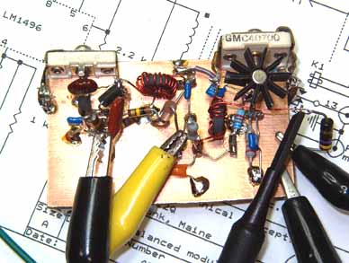
| Here's the TX
pre-driver module, with clip leads and scope probe
attached for preliminary testing. The 2N2222 on the left is the plastic-packaged 1st linear pre-driver. The metal 2N2222 on the right is the linear 2nd pre-driver, fitted with a small black snap-on heatsink. It's required in order to dissipate the heat from the inefficent Class A stage. The carbon resistor on the right-hand edge of the board is a temporary dummy load. |
 |