| Here's the KISS rig's
microphone input-preamplifier and balanced modulator
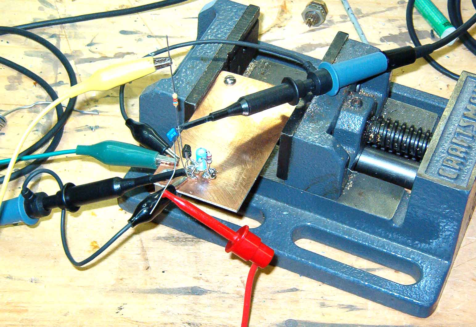
board. The JFET input-amplifier stage is under test for the first time. |
 |
| The LF386 mini-DIP 8-pin op-amp socket is now mounted, along with its miniature gain-setting pot. |  |
| The JFET is coupled to the
op-amp, and power (+12-V) is simultaneously applied to
both stages for preliminary testing. Oscilloscope probes are attached to the input stage (right-hand probe) and output coupling capacitor (probe at upper left-hand corner). |
 |
| It's a long way from Shockley,
Bardeen, and Brattain. A 1-kHz tone is fed into the JFET input coupling network (top trace). Its level is about 100-mV. The bottom trace shows the output of the op-amp into a 10-kohm temporary resistive load. Output level across this load is about 8 Vpp. This test was repeated at increments from 100-Hz to 5-kHz. |
 |
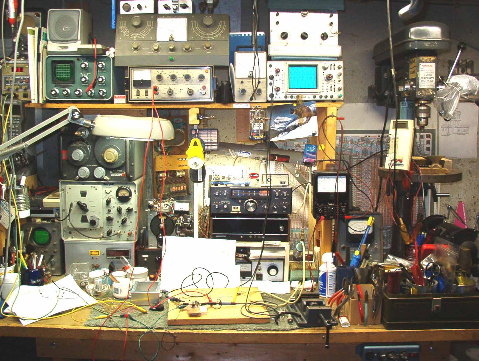
| Here's the messy workbench (ca. 2005) after melting solder and making the microphone amplifier/buffer preliminary tests. |  |
| Click here to return to the home page. | Click here to view more balanced modulator details, including module photographs. |